Description
This guide provides a complete, step-by-step walkthrough for connecting Milesight LoRaWAN sensors to the Siemens Building X cloud platform through the Milesight Gateway and Siemens Desigo CC, using BACnet as the communication protocol.
The integration follows phases:
- Phase 1: Configure the Milesight Gateway — enable BACnet server and map LoRaWAN device data to BACnet objects
- Phase 2: Create a Desigo CC Project — set up a new Desigo CC project with the required extensions
- Phase 3: Connect the Milesight Gateway to Desigo CC via BACnet — discover and import BACnet objects into Desigo CC
- Phase 4: Connect Desigo CC to Building X — onboard the management station and upload device data to the cloud
- Phase 5: Visualize Data in Building X Data Visualizer — create a piece of equipment and build a Data Visualizer dashboard to monitor sensor data
- Troubleshooting Tips
- Disclaimer
Prerequisites
- Milesight Gateway: UG65/UG67 (firmware v60.0.0.45 or later) or UG56 (v56.0.0.5 or later)
- One or more LoRaWAN sensors (e.g., temperature, humidity, energy meters)
- Siemens Desigo CC(v9 or later) with the following extensions installed:
- BACnet Server
- BACnet 3rd Party
- Building X Connector
- Siemens Building X tenant with Devices and Data Setup application access
Phase 1: Configure the Milesight Gateway
1.1 Verify Payload Codec
Before enabling BACnet, ensure the gateway’s payload codec library is version 1.3.5 or later. Navigate to Network Server > Payload Codec to check the version.
If the codec list does not include your devices, create a custom codec following the guide How to Use Payload Codec on Milesight Gateway.
- For receiving device data, the codec must include both a Decoder and an Object Mapping Function.
- For sending downlink commands, it must also include an Encoder and Object Mapping Function.
1.2 Connect LoRaWAN Devices
Connect your LoRaWAN sensor(s) to the Milesight Gateway following How to Connect LoRaWAN Nodes to Milesight Gateway. Ensure the correct payload codec is selected for each device.
1.3 Verify Uplink Packets
Before enabling BACnet, confirm the gateway is receiving and decoding data from your LoRaWAN devices. Navigate to Network Server > Packets to check for uplink packets.
Click Details on a packet to verify the decoder is working — the JSON field should show the decoded sensor data.
1.4 Enable the BACnet Server
Navigate to Protocol Integration > BACnet Server > Server to enable the BACnet server.
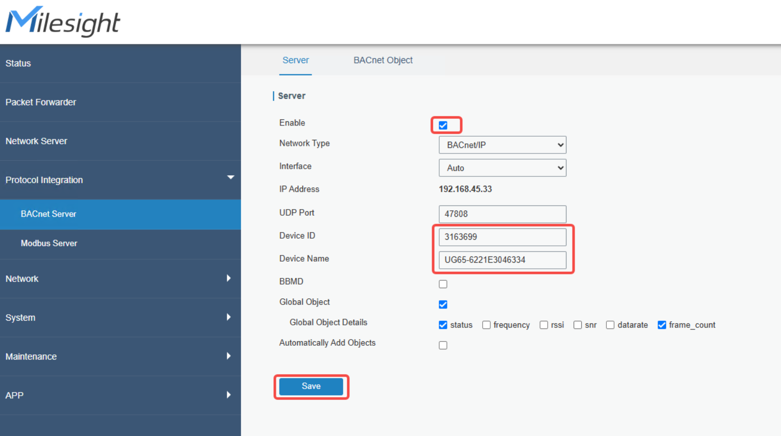
Configure the following settings:
Click Save.
1.5 Add BACnet Objects
Navigate to Protocol Integration > BACnet Server > BACnet Object. Click Add Object to select which LoRaWAN device data points to expose as BACnet objects.
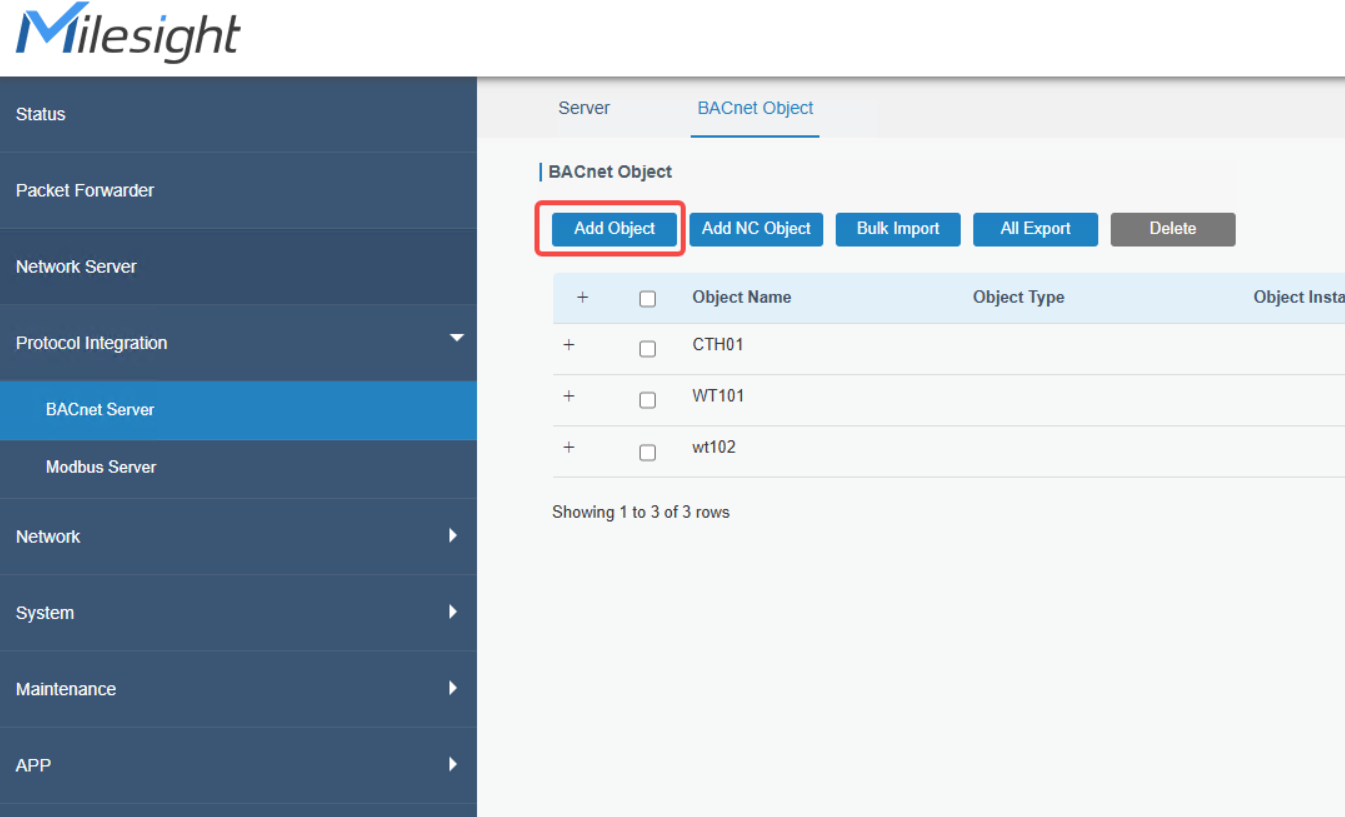
Select the desired device (e.g., WT101) and check the individual data points you want to expose. Each point is mapped to a BACnet object type — for example,
battery becomes an Analog-Input (in %),
device_status becomes a Binary-Input
temperature becomes an Analog-Input (in °C).
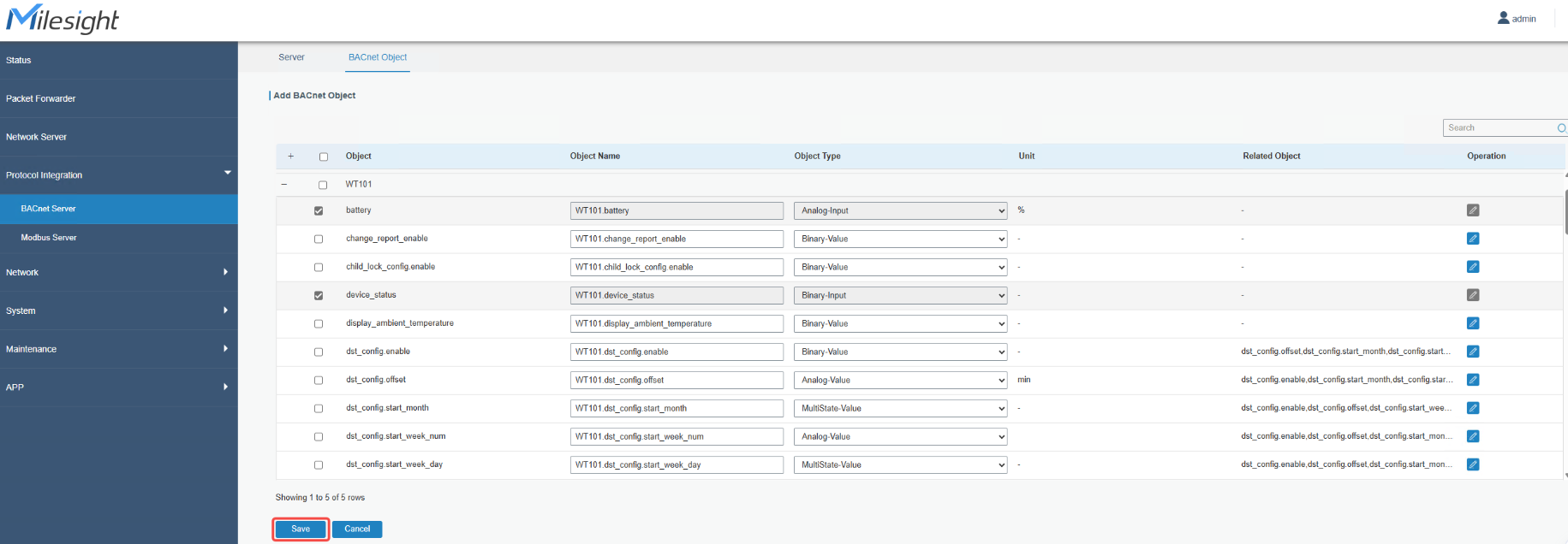
Click Save to confirm.
1.6 Verify BACnet Object Values
After saving, return to the BACnet Object page and verify that the Present Value column is being updated with live sensor data.
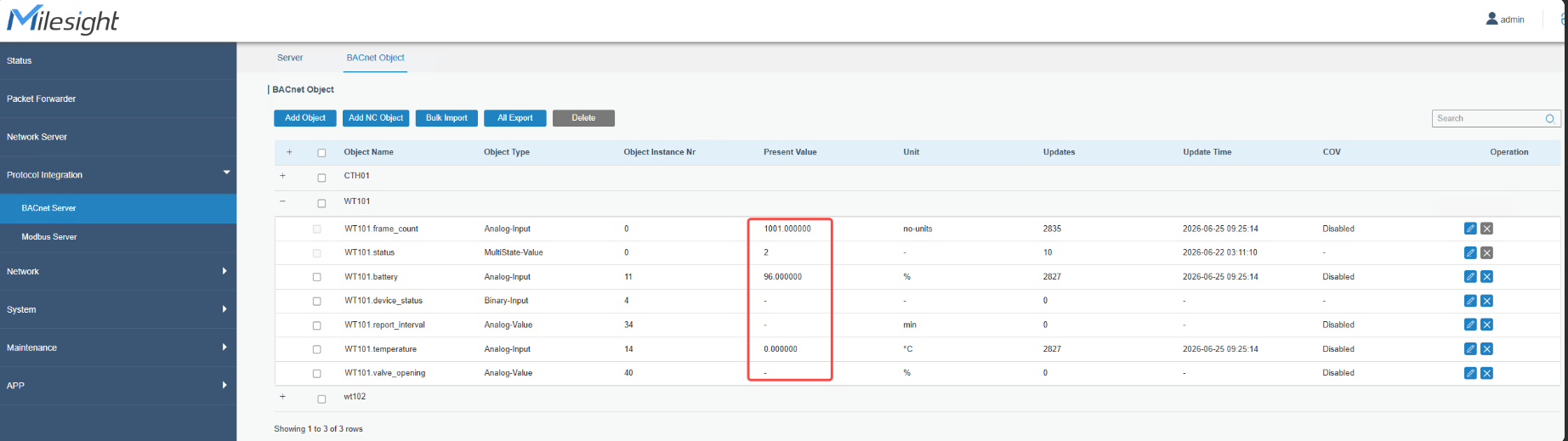
Note: Some objects may show a blank Present Value because they are used only for sending downlink commands, not for receiving data.
Phase 2: Create a Desigo CC Project
2.1 Open System Management Console
Launch the Siemens System Management Console (SMC). The Projects panel shows the list of existing projects.
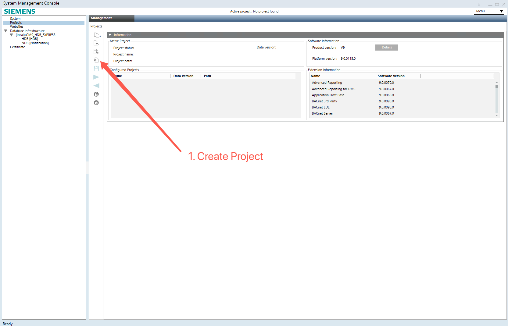
Click the New Project button to start the project creation wizard.
2.2 Step 1 — Server Project Information
In the New Project wizard (Step 1 of 3), fill in the server project details:
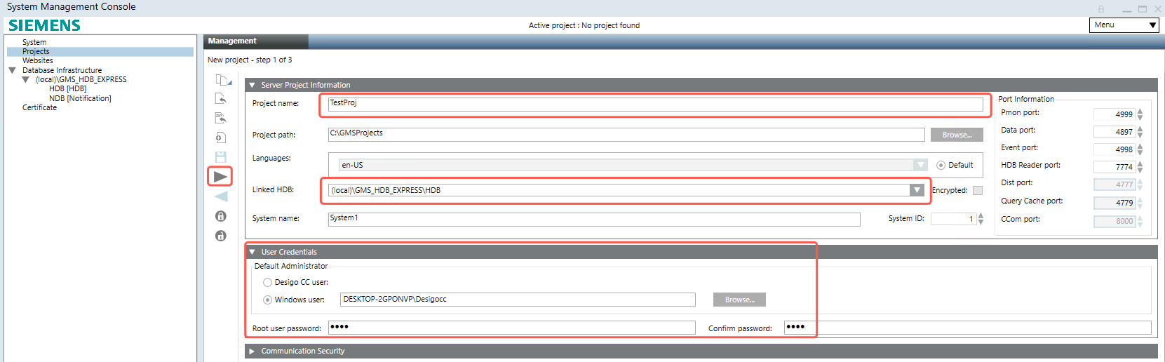
- Project name: Enter a descriptive name (e.g., TestProj)
- Project path: Set the directory where the project files will be stored (e.g., C:)
- Languages: Select the project language (e.g., en-US)
- Linked HDB: Select the linked Host Database (e.g., (local)_HDB_EXPRESS)
- System name and System ID: Default values are acceptable
- User Credentials: Choose whether to use a Desigo CC user or a Windows user for the Default Administrator. Enter the root user password and confirm it.
2.3 Step 2 — Web Services Communication
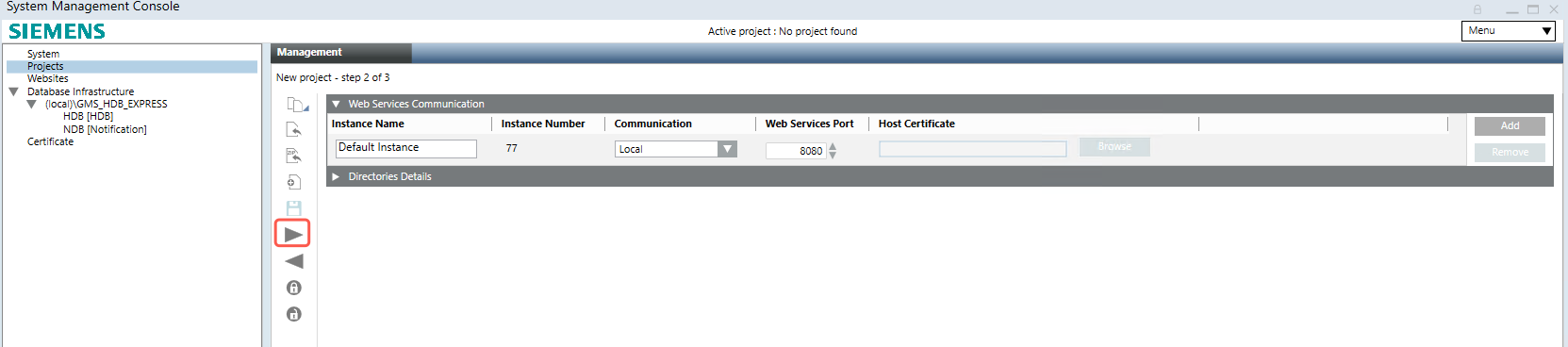
Configure the Web Services Communication settings. The default instance (port 8080, Local communication) is typically sufficient. Expand Directories Details to verify the project directories.
2.4 Step 3 — SQL Server Details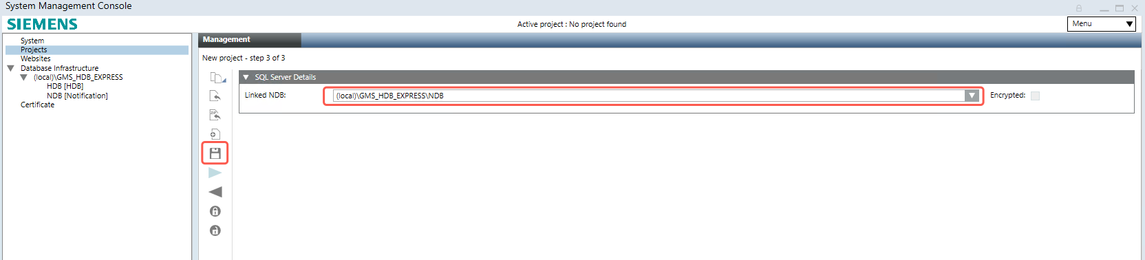
Set the Linked NDB (Notification Database) to the appropriate SQL Server instance (e.g., (local)_HDB_EXPRESS). Click Save (floppy disk icon) to create the project.
2.5 Select Project Extensions
After creating the project, the Select Project Extensions dialog appears. Under Connectivity, enable the following extensions:
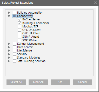
- BACnet Server
- Building X Connector
Click OK to confirm. The project is now ready to be started.
Phase 3: Connect the Milesight Gateway to Desigo CC via BACnet
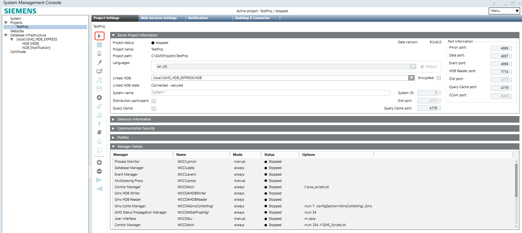
3.1 Start the Project
In the SMC, select your project and click the Start Project button. The project status changes from “stopped” to “started”.
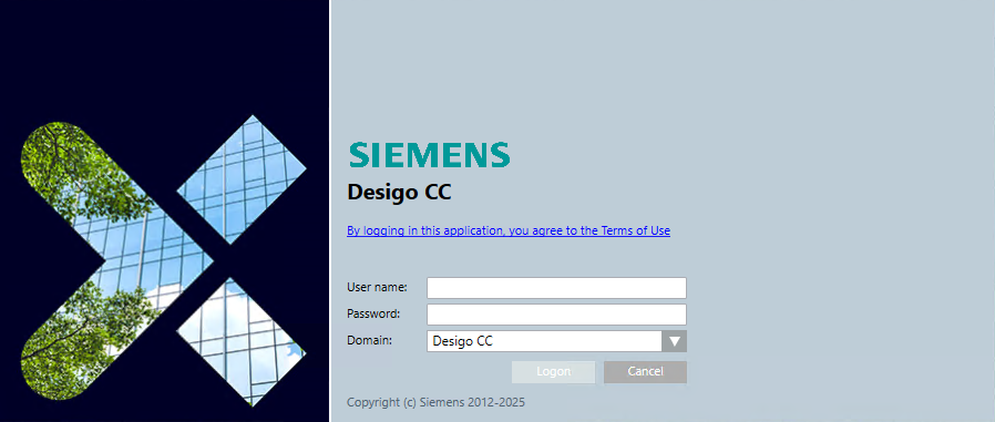
3.2 Log in to Desigo CC
Launch the Desigo CC System Manager application and log in with your credentials.
3.3 Add a BACnet Driver
Ensure System Manager is in Engineering mode. In the System Browser, select Management View.
Navigate to Project > Management System > Servers > Main Server > Drivers. Click the New button in the Object Configurator and select New BACnet Driver.
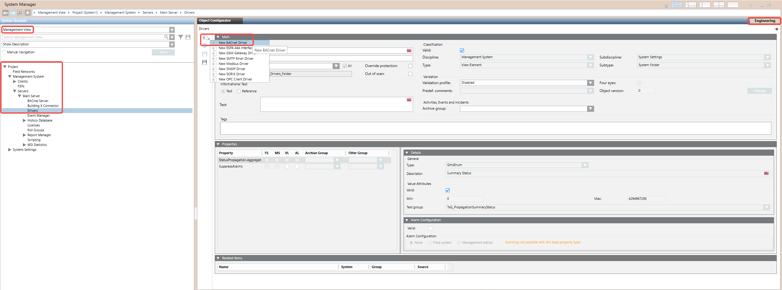
In the New Object dialog, enter a name and description (e.g., Gms Bacnet Driver 1) and click OK.
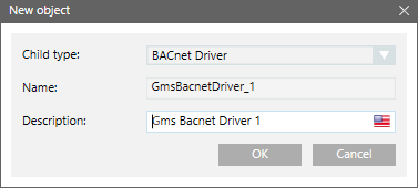
The BACnet Driver object appears in the System Browser but is not yet running. Click the BACnet tab to configure the BACnet stack.
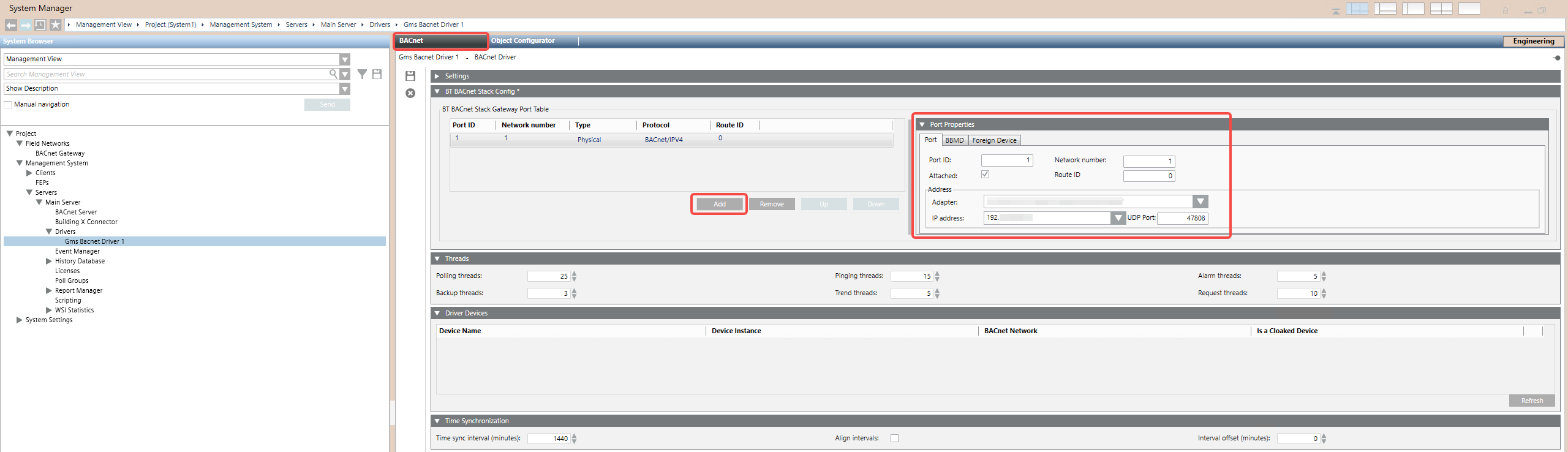
In the Port Properties section, configure:
- Port ID: 1
- Network number: 1
- Adapter: Select the appropriate network adapter
- IP address: The IP address of the Desigo CC machine
- UDP Port: 47808 (standard BACnet/IP port)
Click Add to add the port entry.
3.4 Start the BACnet Driver
Click the Extended Operation tab. In the Manager Status property row, click Start to start the driver.
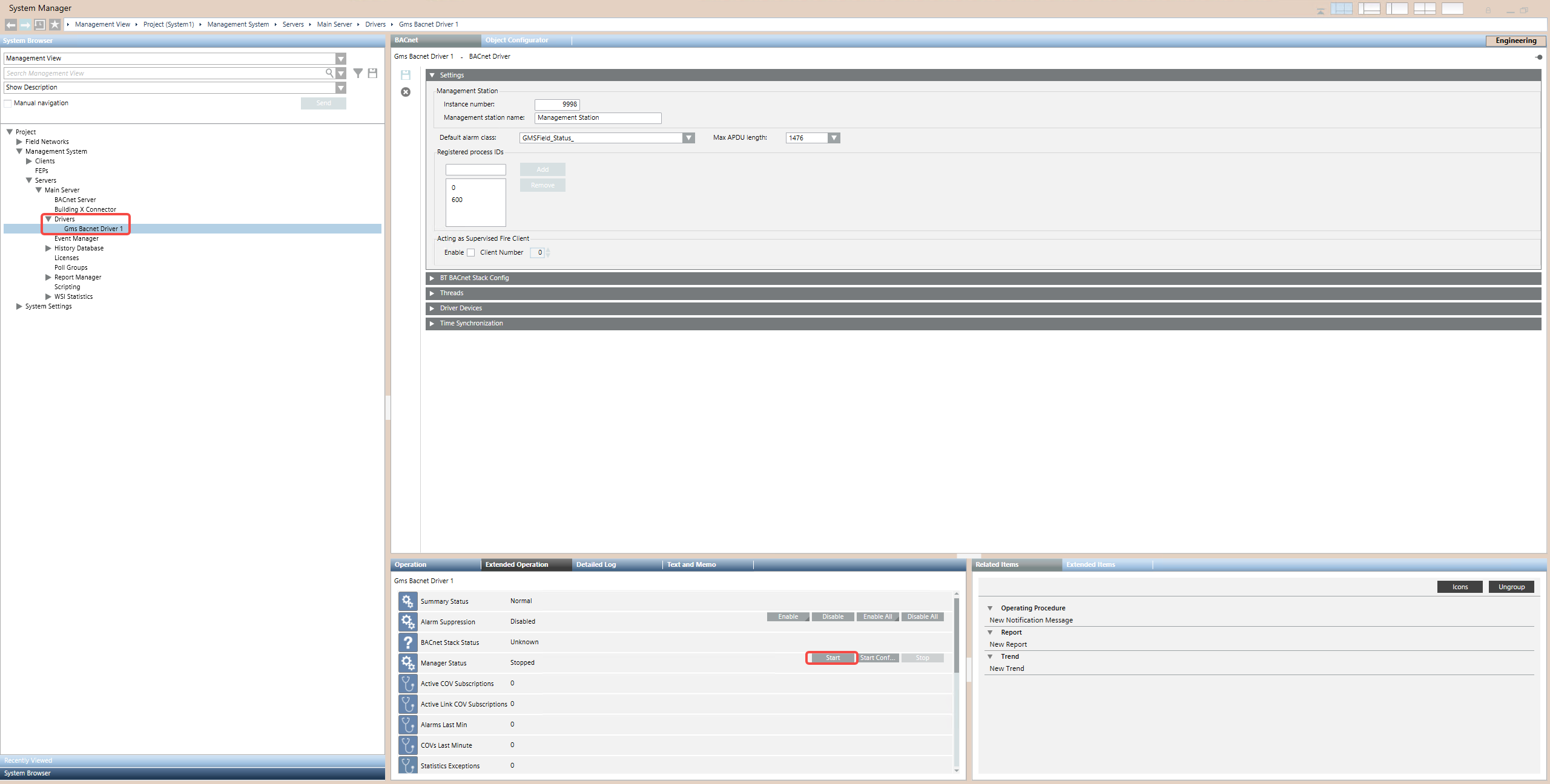
The Manager Status should change to Normal, indicating the BACnet driver is running.
3.5 Add a BACnet Network
In the System Browser, navigate to Project > Field Networks. Click New and select New BACnet Network.
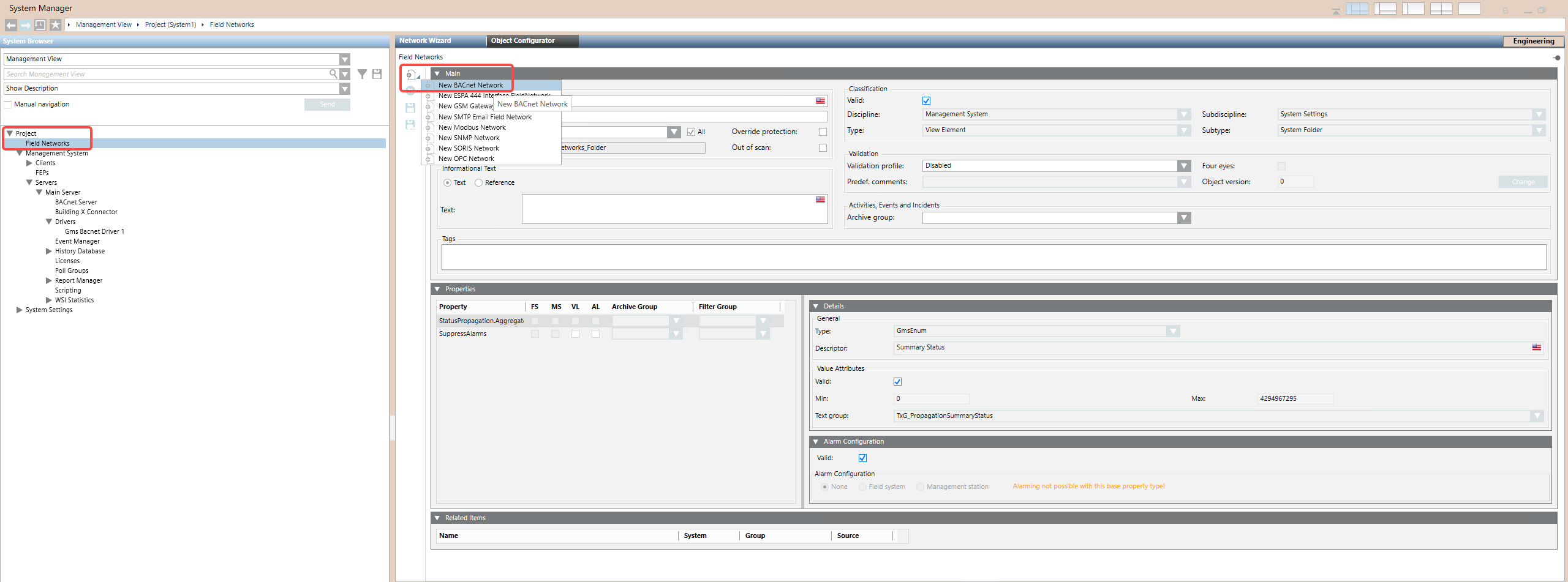
In the New Object dialog, enter a name and description (e.g., BACnetGateway) and click OK.
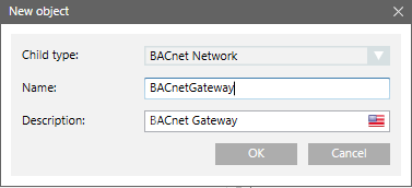
3.6 Assign the Driver to the BACnet Network
With the new BACnet Network selected, click the BACnet tab. In the Network Setting section, use the Monitored by driver dropdown to select the BACnet driver you created earlier (e.g., Gms Bacnet Driver 1). Click Save.
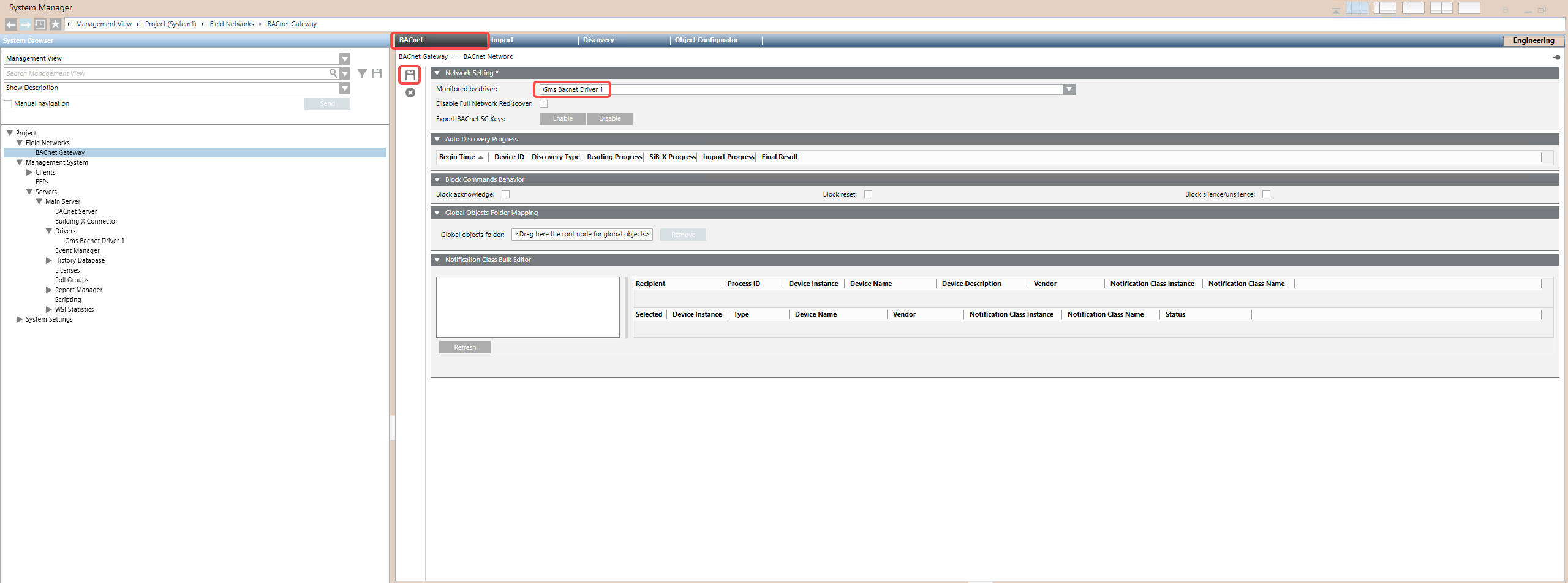
3.7 Scan for BACnet Devices
Navigate to the Discovery tab of the BACnet Network. Expand the Device Discovery section and click Scan.
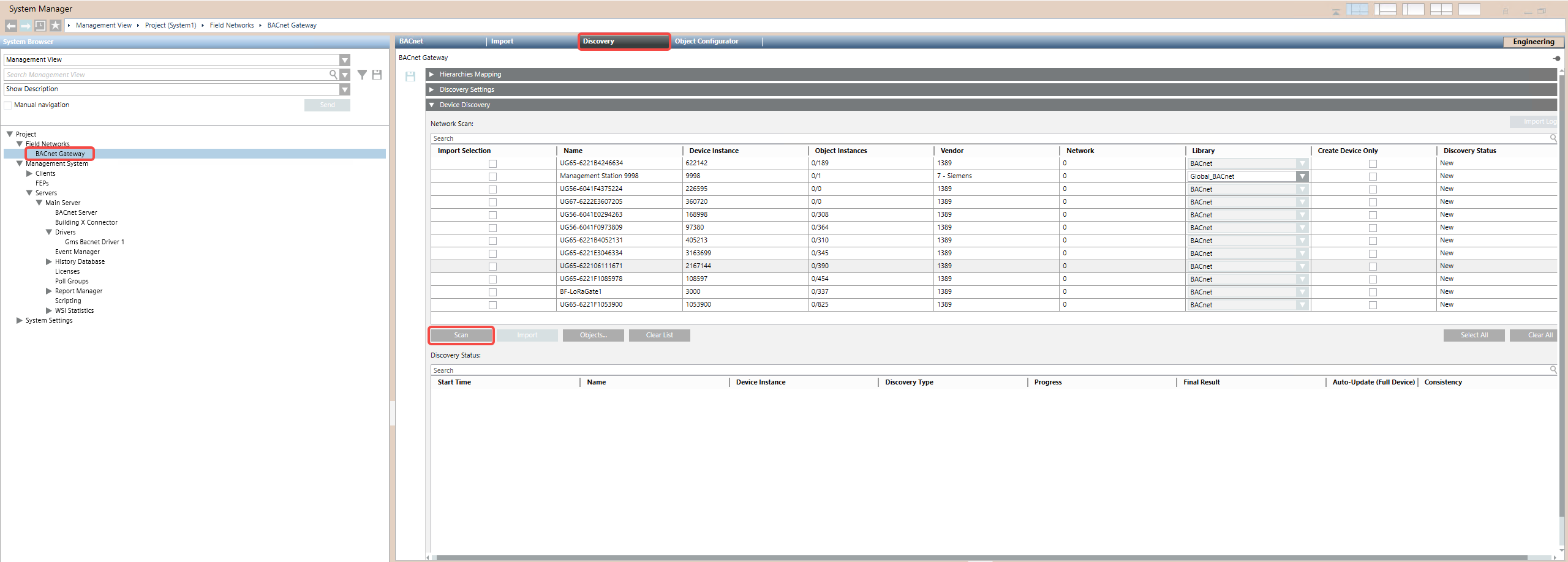
The Milesight Gateway should appear in the Network Scan section as a discovered BACnet device (identified by its Device ID). Wait for the scan to complete or click Cancel to stop early.
3.8 Import BACnet Objects
For each discovered device, check the Import Selection checkbox to mark it for import.
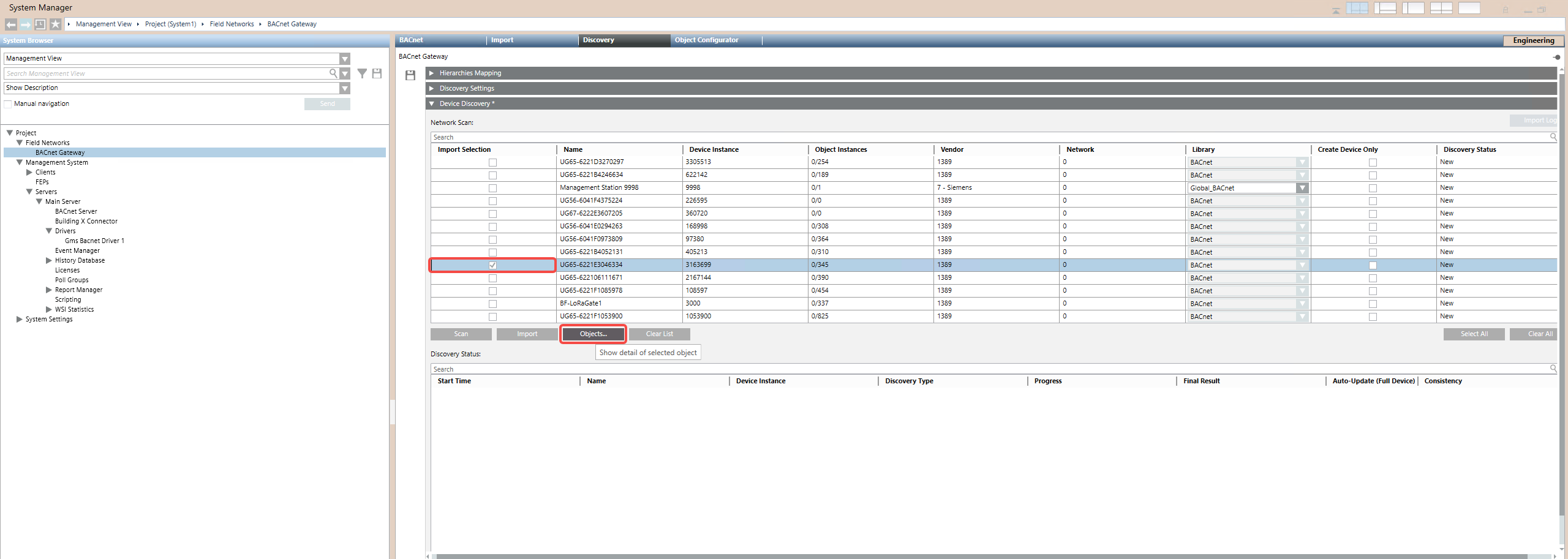
To limit which BACnet objects are imported from a third-party device, click Import Selection, then click Objects. Select only the objects you want to include (e.g., battery, device_status, temperature) and click Save, then Back.
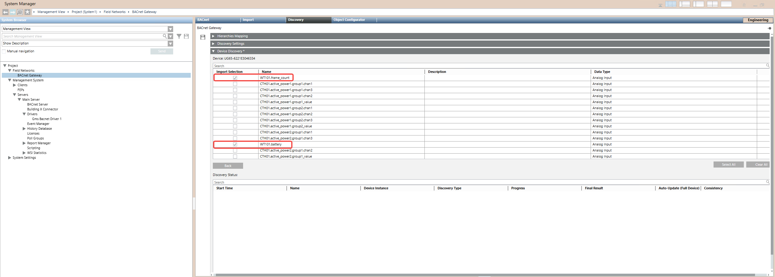
After configuring the import selections, click Save to begin the import process. Monitor the Discovery Status section for progress.
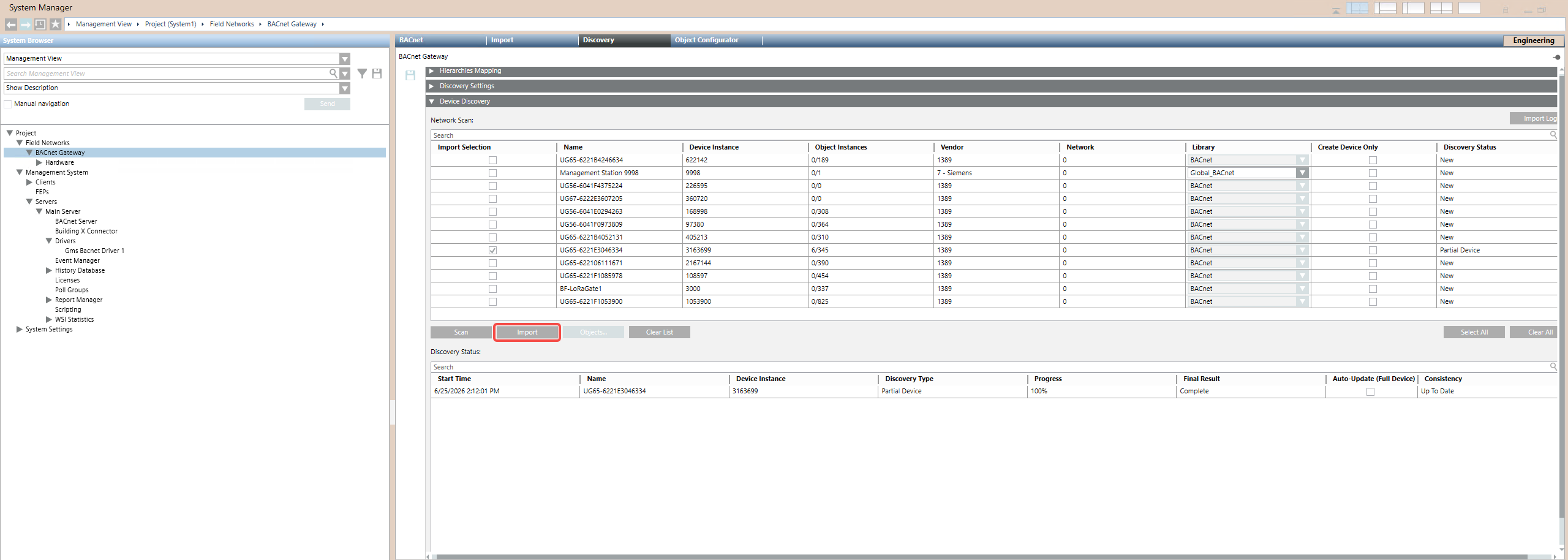
Note: Importing may take from a few seconds to several minutes depending on the number of objects.
3.9 Verify Imported Objects
Once the import is complete, the BACnet objects from the Milesight Gateway appear in the System Browser under Field Networks > BACnet Gateway > Hardware > Local_IO. Click on an individual object to inspect its properties.
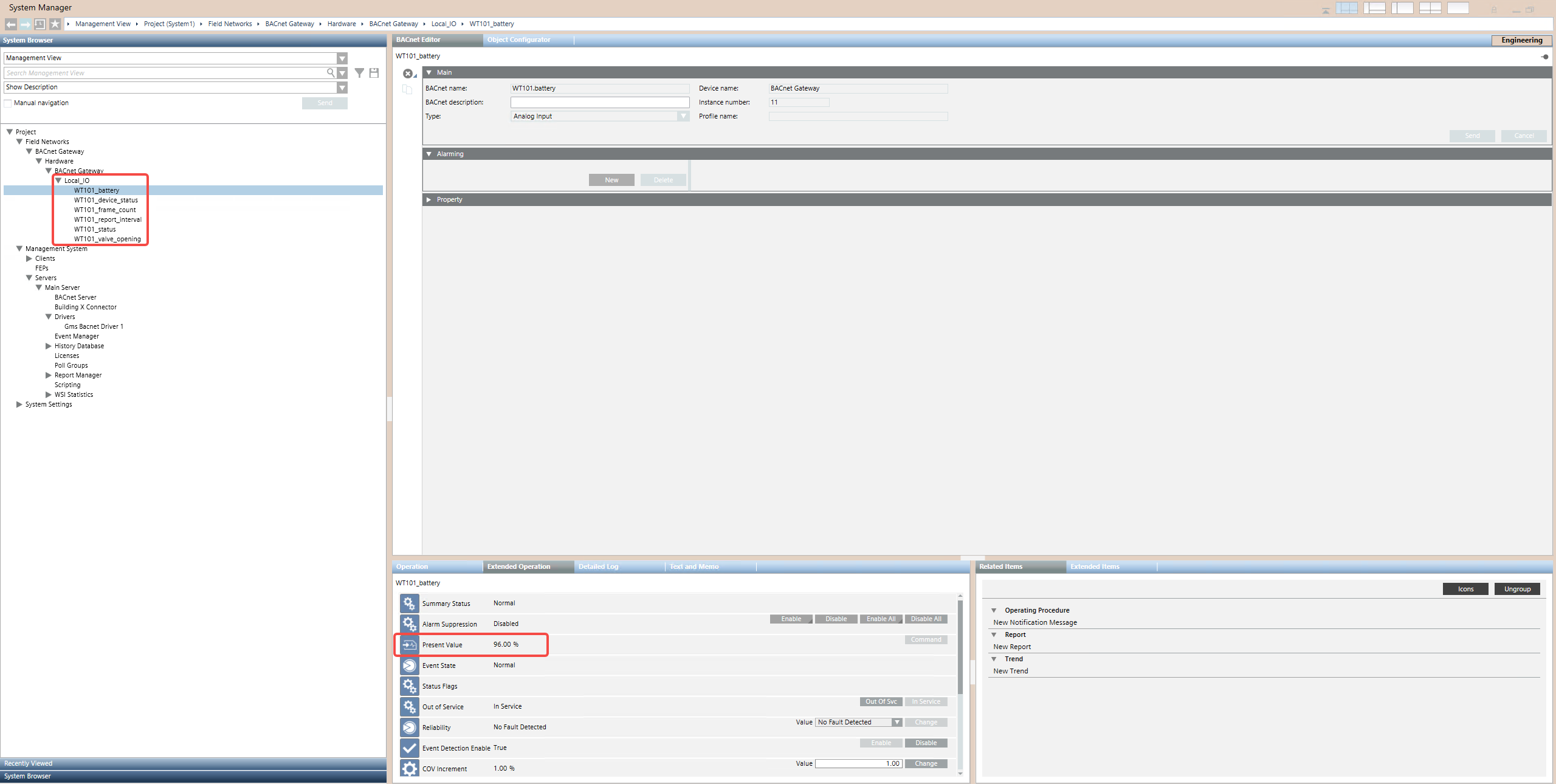
Verify that the Present Value reflects live sensor data (e.g., 96.00% for the WT101 battery level).
Phase 4: Connect Desigo CC to Building X
4.1 Create a Software User Account
Before configuring the Building X Connector, create a Software Account user that Building X will use to access Desigo CC data.
Navigate to Project > System Settings > Users. Click New.
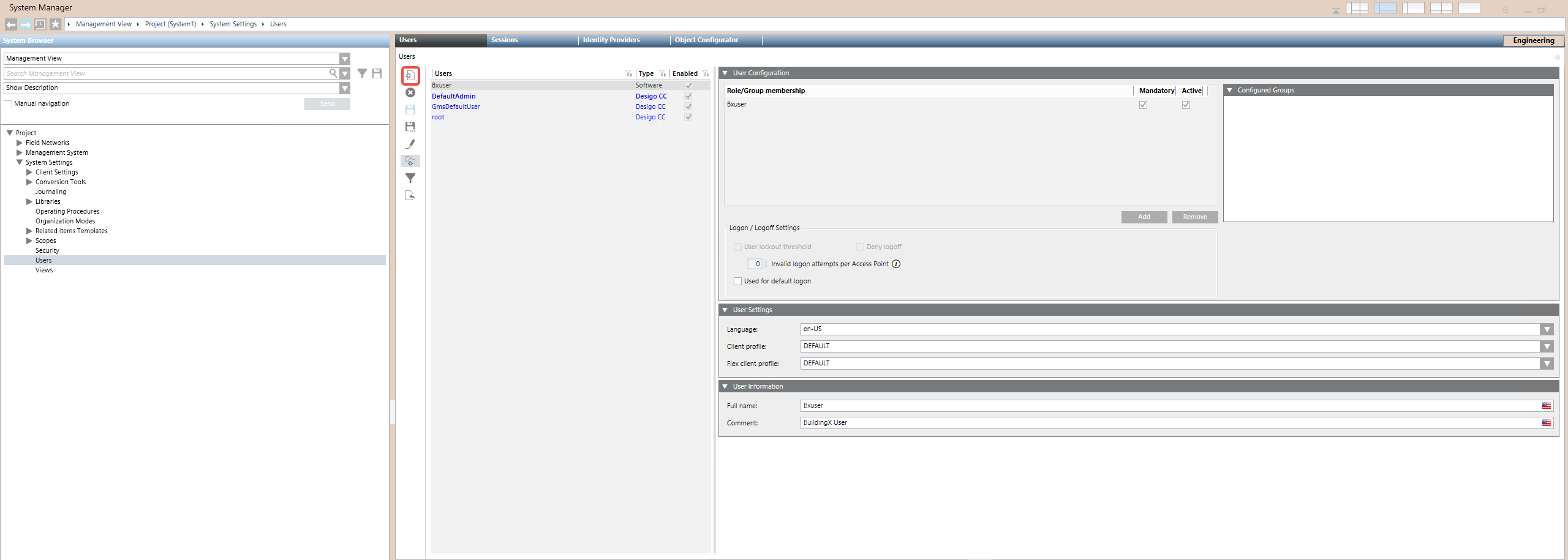
In the New User dialog, set: - User type: Software account - User name: A descriptive name (e.g., Bxuser)
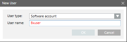
Click OK, then Save. This user account determines which objects and events are sent to Building X. All commanding from Building X applications will execute with this user’s privileges.
4.2 Configure the Building X Connector
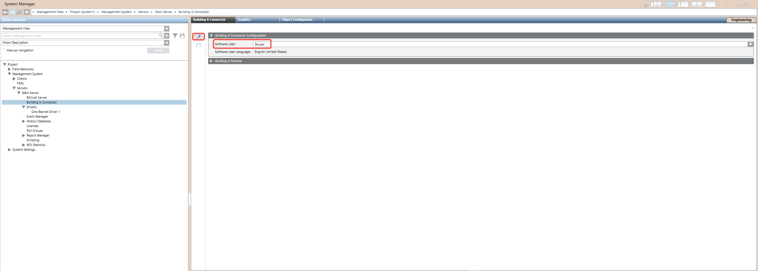
In the System Manager, navigate to Project > Management System > Servers > Main Server > Building X Connector. Select the Building X Connector tab and click Edit.
4.3 Start the Connector Agent
Switch to the System Management Console (SMC). Select your project and click the Building X Connector tab. In the Communication Settings section, verify the Control and Application ports (default: 43123 and 43124). Click Start Agent from the toolbar.
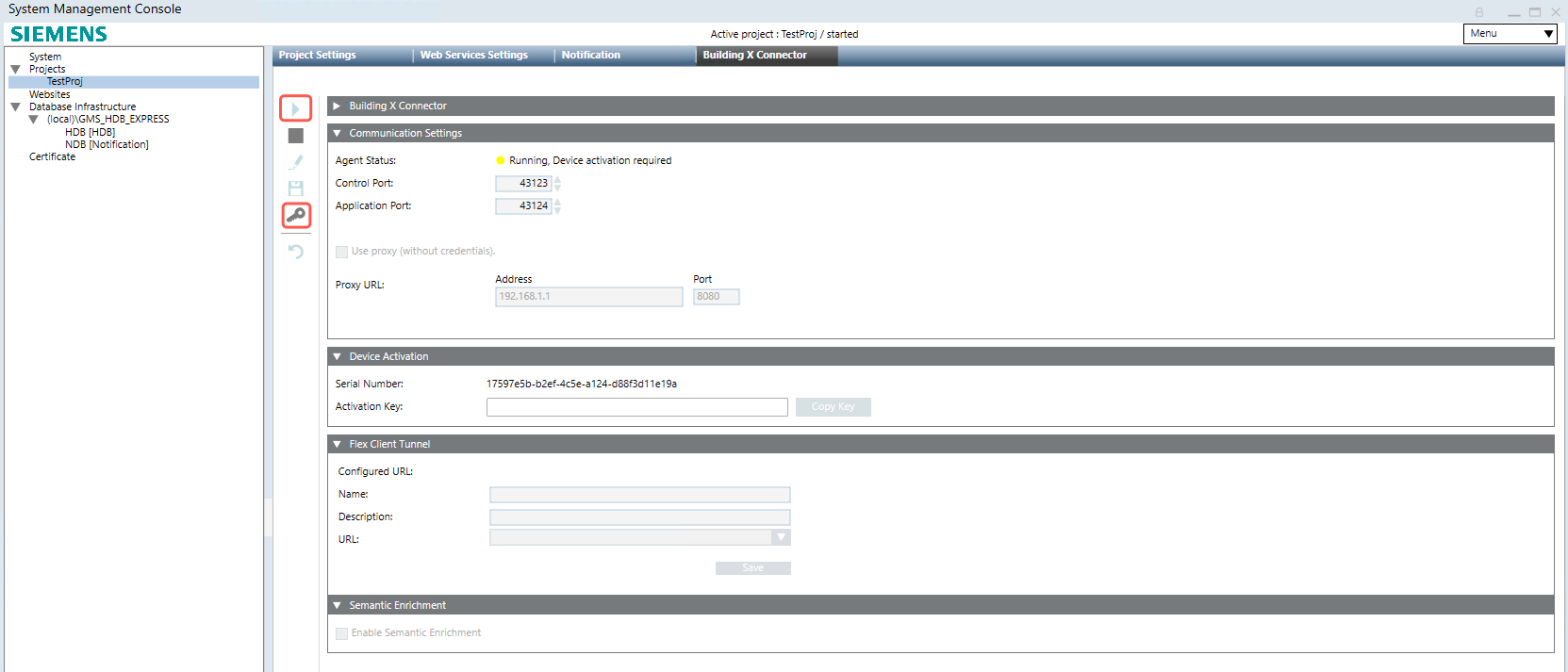
The Agent Status should display “Running, device activation required”. Then Click Generate Key from the toolbar. In the Device Activation section, click Copy Key to copy the activation key to the clipboard.
Note: If you are running more than one Desigo CC project on the same machine, each project’s Building X Connector must use a unique set of ports.
4.4 Onboard to Building X
Log into the Building X Devices application. Navigate to Sites and either select an existing site or create a new one (e.g., “Milesight Test”).
Click Add to add a new device. Select With activation key, paste the key you copied from Desigo CC, and click Validate.
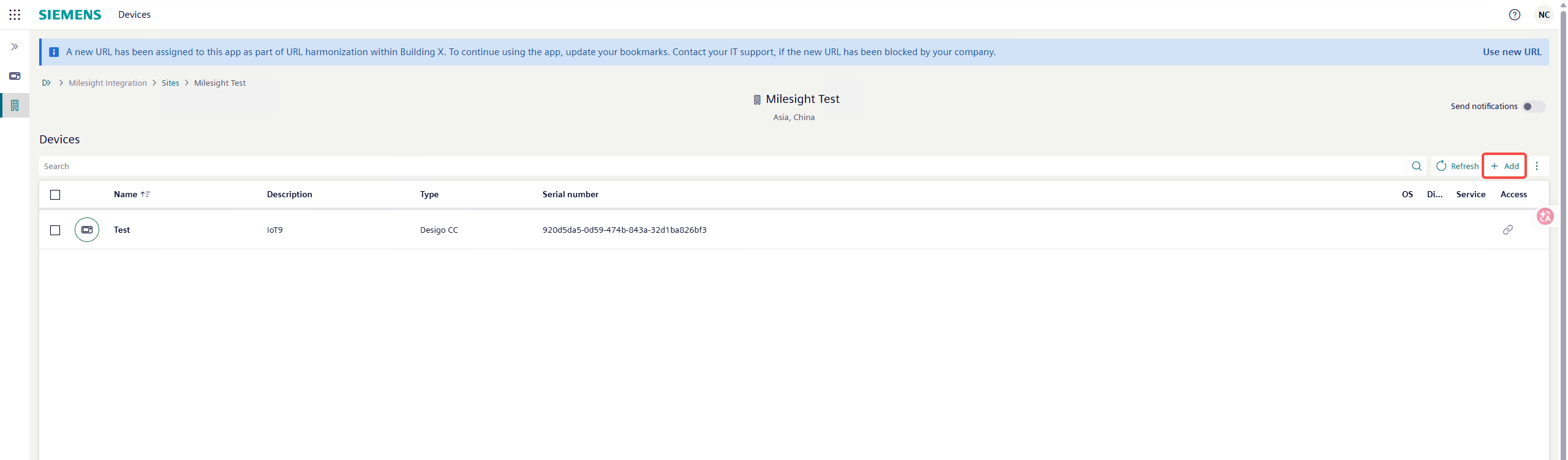
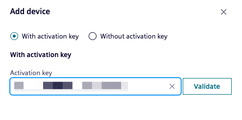
Once the key is validated, complete the Custom name and Custom description fields, and click Add.
Note: If you are re-onboarding a Desigo CC project, you can select “Use this device as a replacement” to retain historical point data, or leave it unchecked for a clean start.
4.5 Assign Distribution and Synchronize
In the Assign distribution dialog, select Desigo CC/Cerberus DMS and click Save.
Navigate to the Applications tab for the newly added device. Check the Install checkbox for the DesigoCC application, then click Synchronize.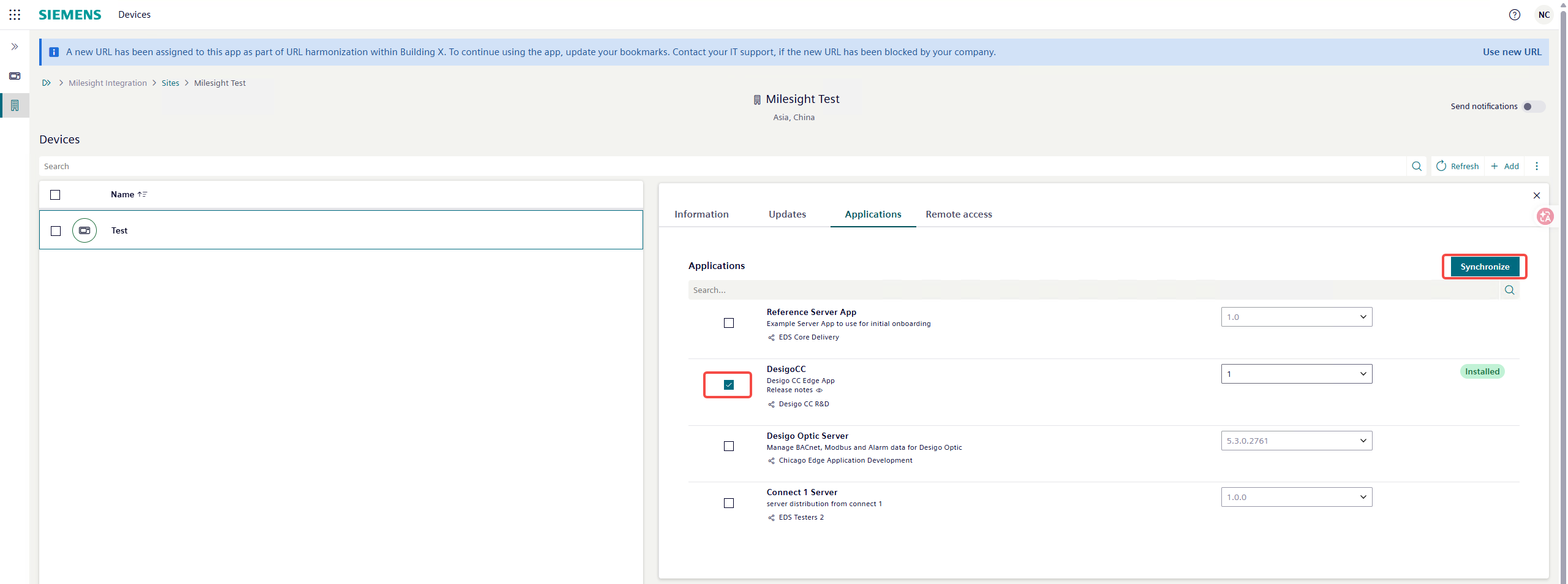
4.6 Verify Connection
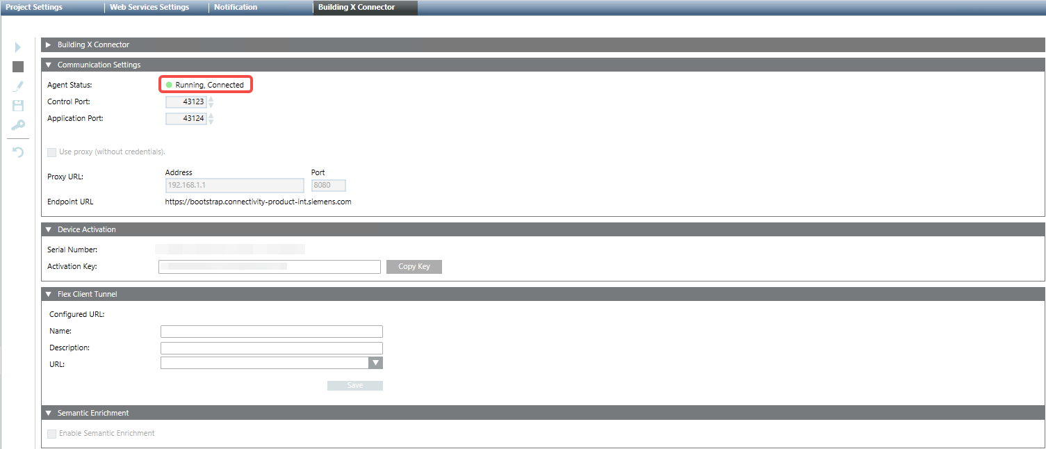
Return to the SMC and check the Building X Connector tab. The Agent Status should now display Running, Connected. If it shows any other status, refer to the Troubleshooting section of the Building X Connector documentation.
4.7 Export, Discover, and Upload Data Points
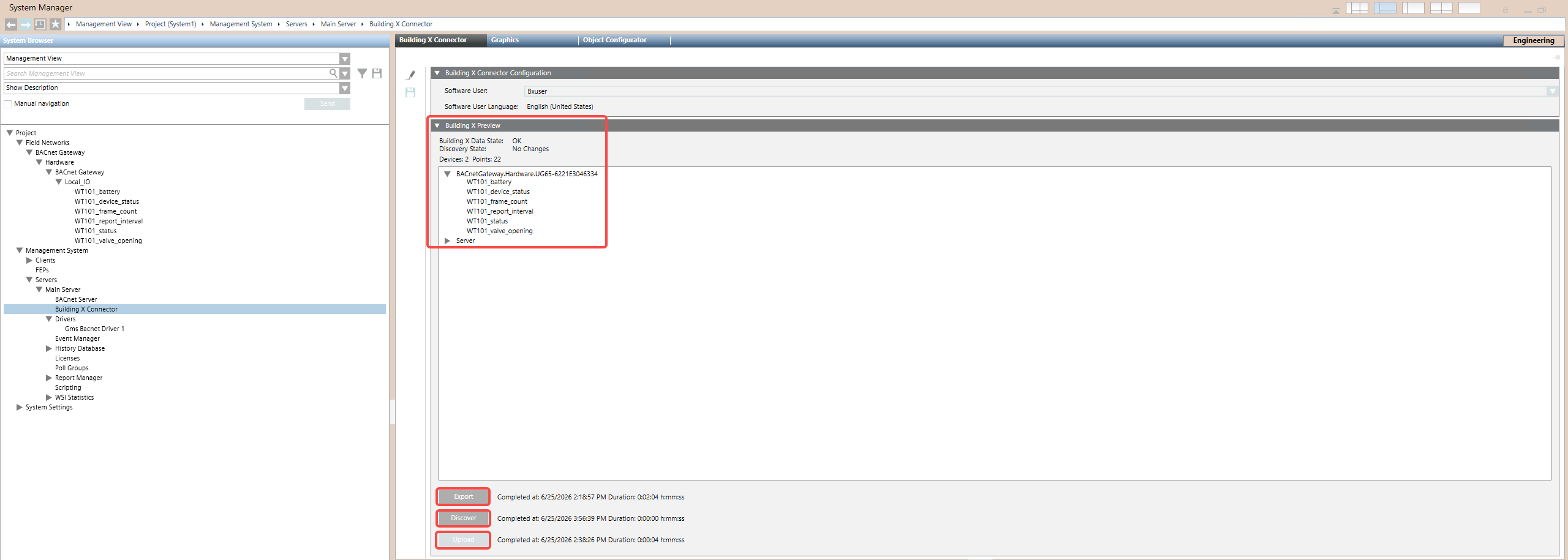
Back in the System Manager, go to the Building X Connector tab. The Building X Preview pane shows the current data state and discovered devices/points.
Export
Click the Export button to create a bundle of Desigo CC device and point data for the discovery process. The export reflects the current device configuration — if you make configuration changes (adding, removing, or modifying devices/points), you must perform another export.
Discover
Once the export completes and the Operational State is Ready, click Discover. An expandable list of devices and data points appears in the Building X Preview pane, along with counts.
Verify that the discovered devices and points match your expectations. If the count is wrong, check your scope configuration (security groups and user privileges), then re-export and re-discover.
Upload
Click Upload, then OK to upload all discovered points to Building X. The button is disabled when there are no changes (“No Changes”).
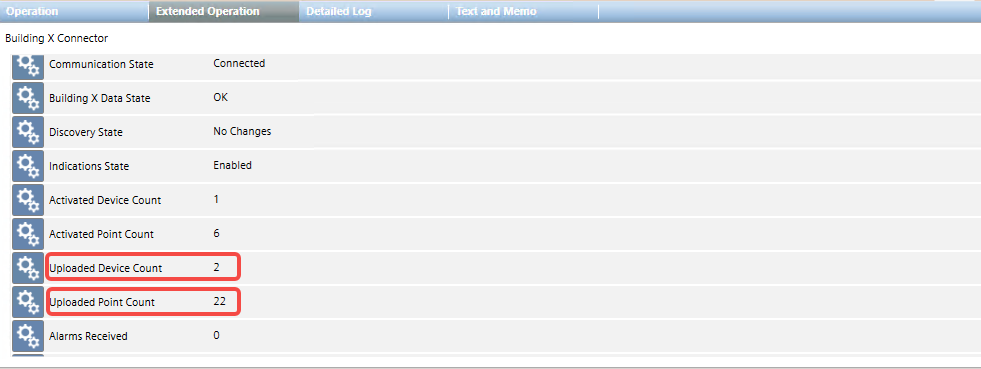
Check the Extended Operation tab for upload statistics — it shows the uploaded device count and uploaded point count.
4.8 Activate Data Points in Building X
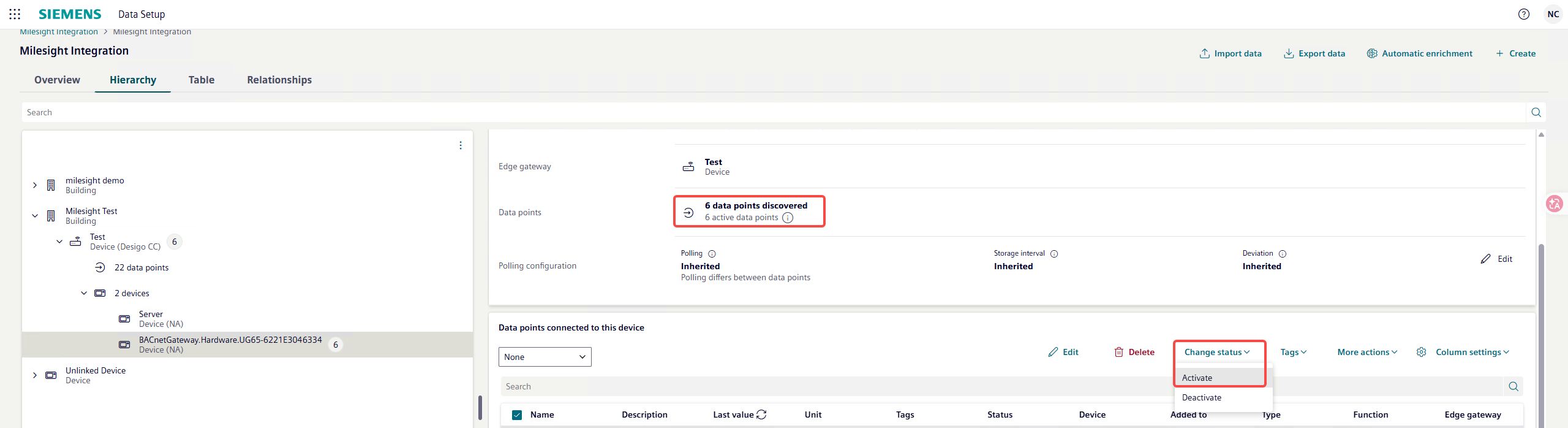
By default, all data points are uploaded to Building X in a deactivated state. You must activate them before they can be managed.
Open the Building X Data Setup application. Navigate to the site and device. Under Data points connected to this device, use the Change status dropdown and select Activate.
4.9 Verify Data in Building X
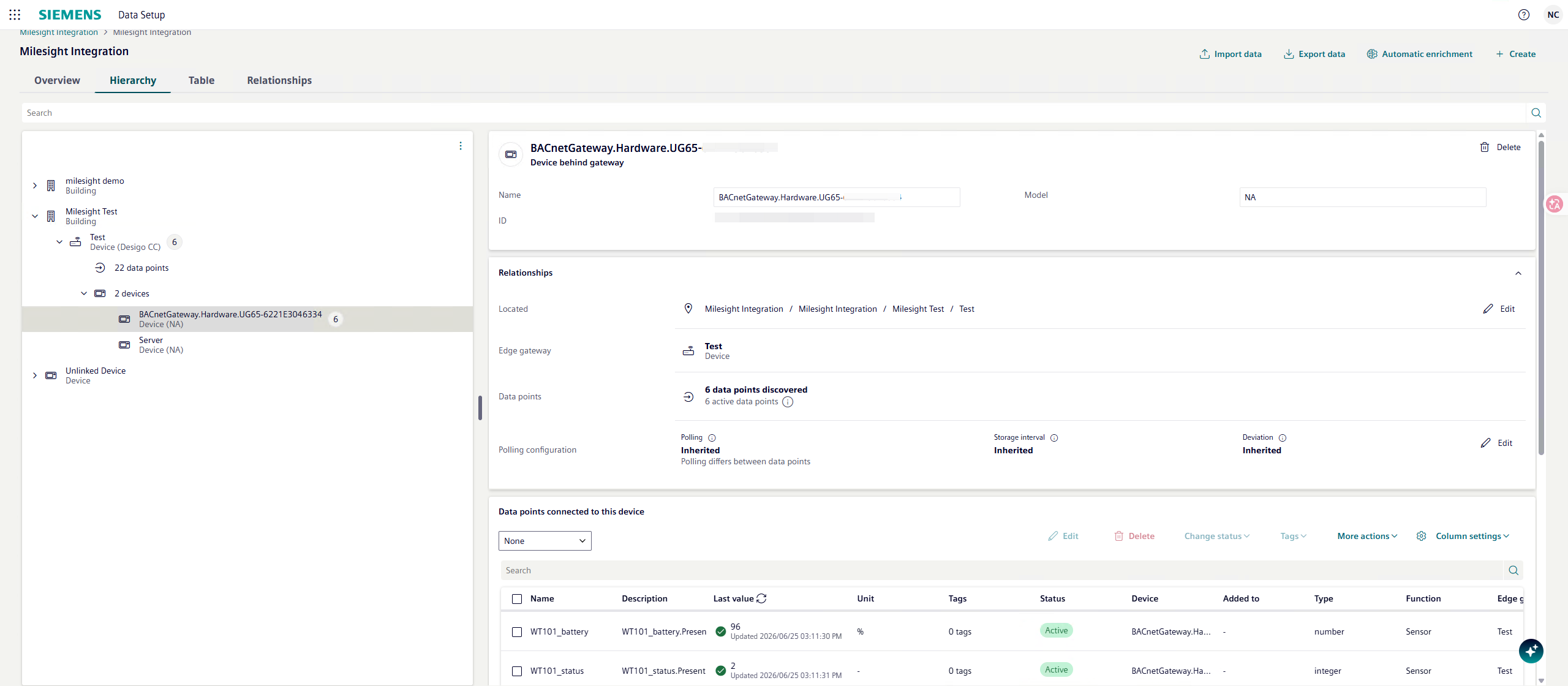
Once activated, open a Building X application such as Operations Manager to monitor the current values and start commanding your devices. The data from your Milesight LoRaWAN sensors is now visible and manageable in the Building X cloud platform.
Phase 5: Visualize Data in Building X Data Visualizer
5.1 Create a Piece of Equipment
Before creating a dashboard, you need to create a piece of equipment in the Data Setup application and assign the relevant data points to it.
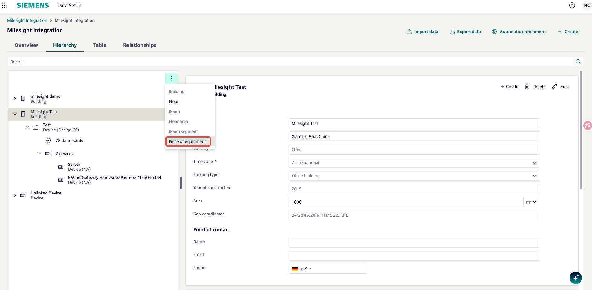
Open the Data Setup application. In the Hierarchy tab, navigate to the building that contains your uploaded devices. Click the three-dot menu (⋮) on the building entry and select Piece of equipment from the dropdown.
In the New equipment form, fill in the required fields:
- Name: A descriptive name (e.g., WT101-Battery)
- Discipline: Select the appropriate discipline (e.g., system-test)
- Type: Select the equipment type (e.g., OM TestEquipment)
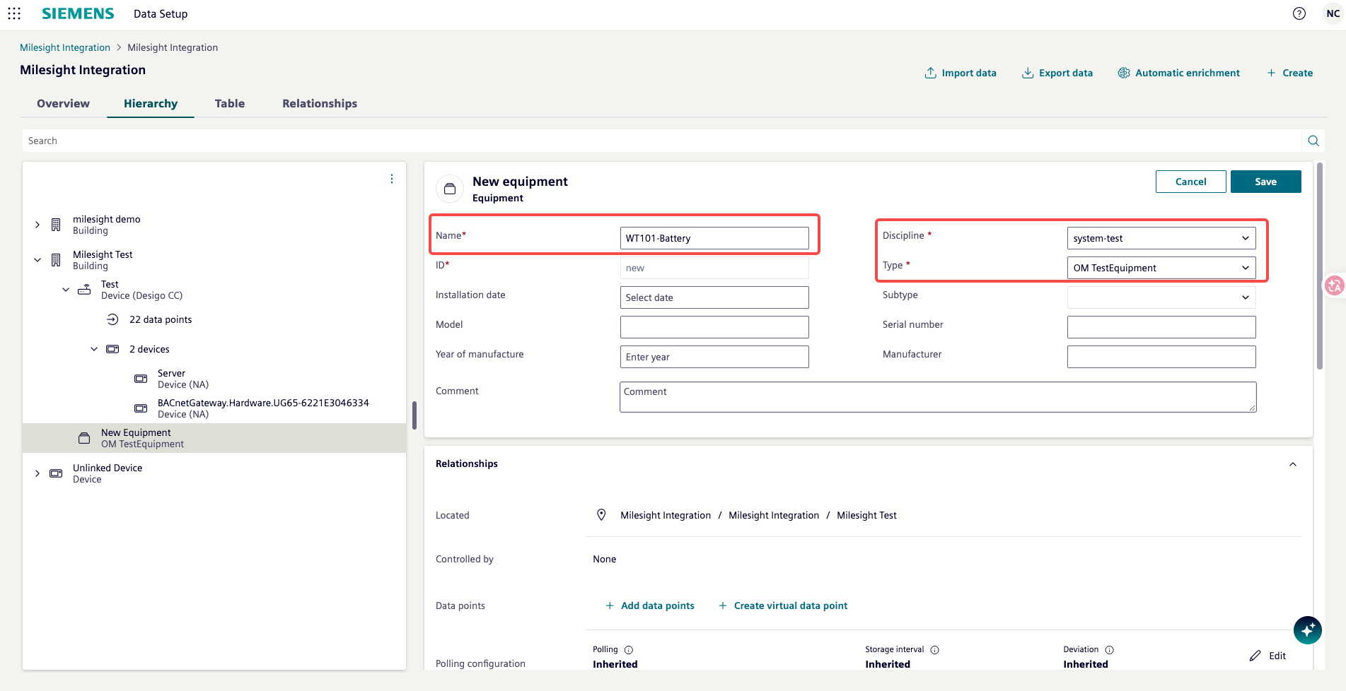
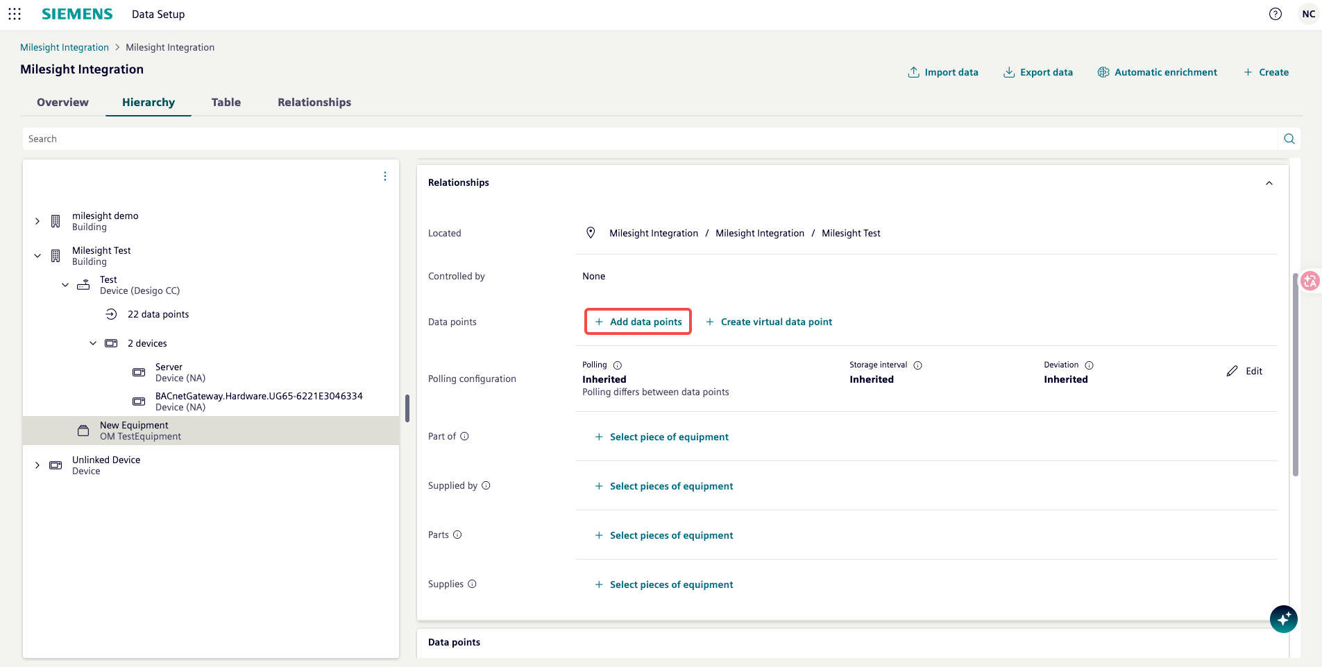
Scroll down to the Relationships section. Under Data points, click + Add data points to link sensor data from the Milesight Gateway to this piece of equipment.
In the Add data points dialog, select the Edge gateway (e.g., Test) and the corresponding Device (e.g., BACnetGateway.Hardware.UG65-6221E3046334). Browse the list of available data points and check the box next to the point you want to add (e.g., WT101_battery). Click Assign.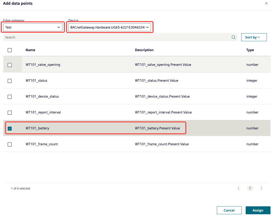
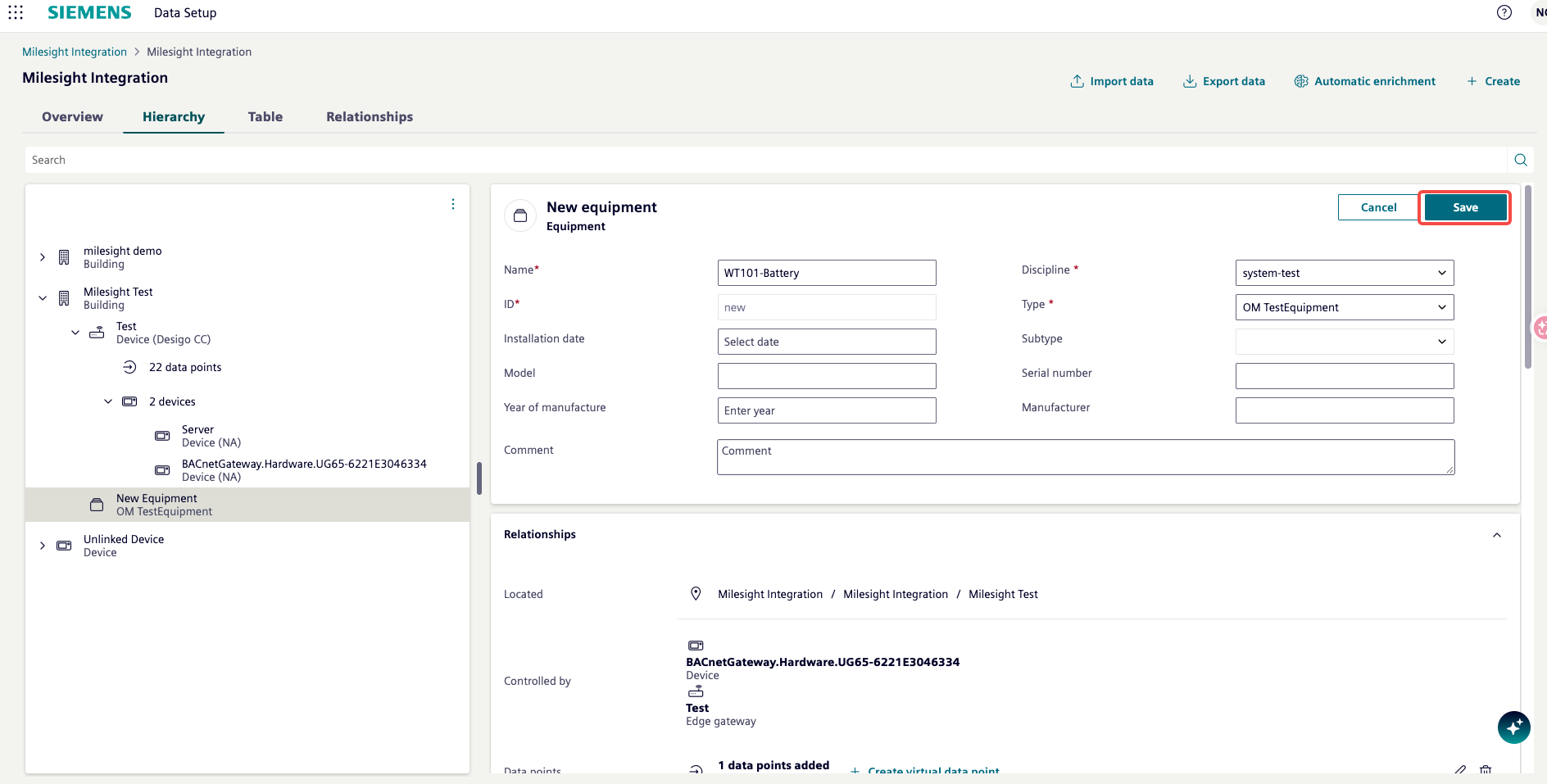
After assigning the data points, the Relationships section will show the device under Controlled by and the data point count. Click Save in the top-right corner to save the piece of equipment.
5.2 Create a Data Visualizer Dashboard
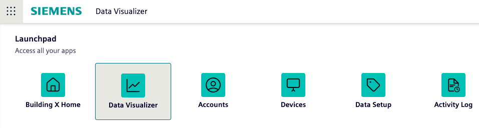
Open the Building X Launchpad and click the Data Visualizer app.
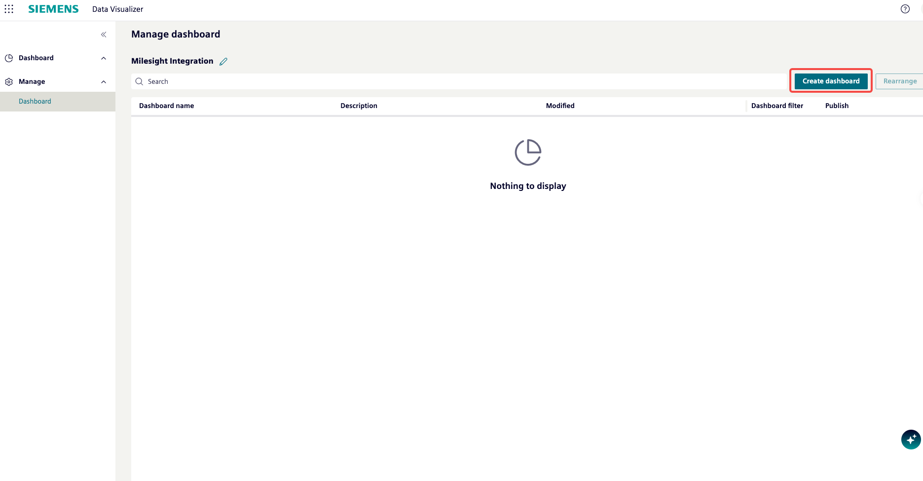
In the Data Visualizer, navigate to Manage > Dashboard. If no dashboards exist yet, the list will show “Nothing to display.” Click Create dashboard in the top-right corner.
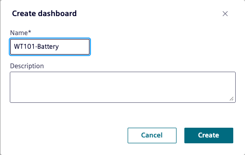
In the Create dashboard dialog, enter a name (e.g., WT101-Battery) and an optional description. Click Create.
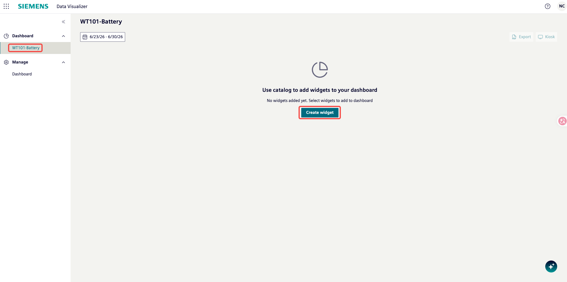
The new dashboard opens. Since no widgets have been added yet, it shows “Use catalog to add widgets to your dashboard.” Click Create widget.
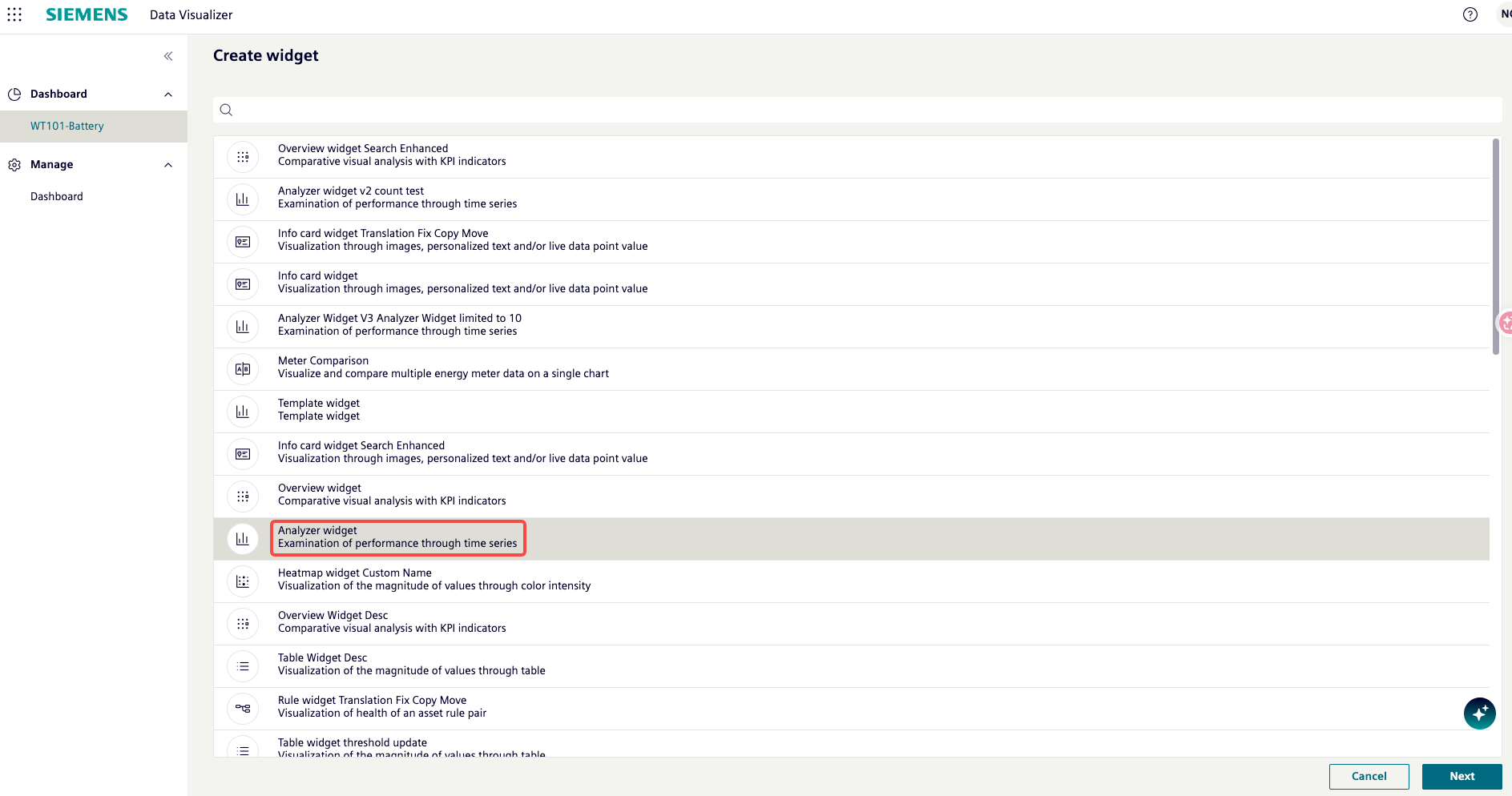
The widget catalog opens with a list of available widget types. Select Analyzer widget (Examination of performance through time series) and click Next.
In the widget configuration screen, set the widget name (e.g., Analyzer widget). In the Building hierarchy panel, navigate to the building and select the piece of equipment you created earlier (e.g., Milesight Test > WT101-Battery). In the Data points panel, the available data points for that equipment will appear. Click the + button next to the data point (e.g., WT101_battery) to add it to the chart.
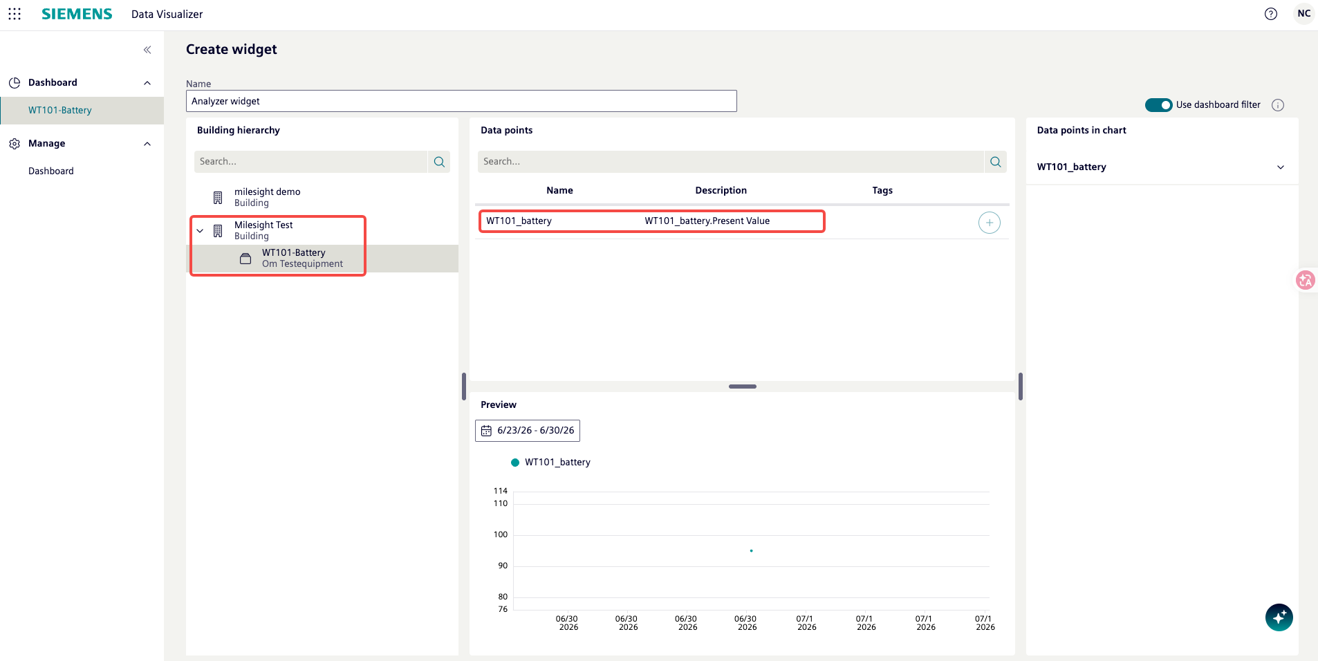
A preview of the chart appears at the bottom of the screen. Once satisfied with the configuration, click Save in the top-right corner.
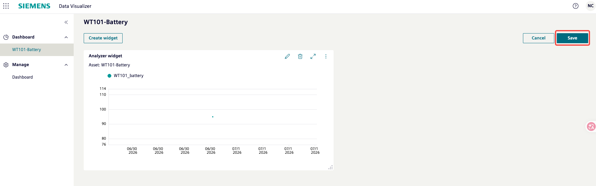
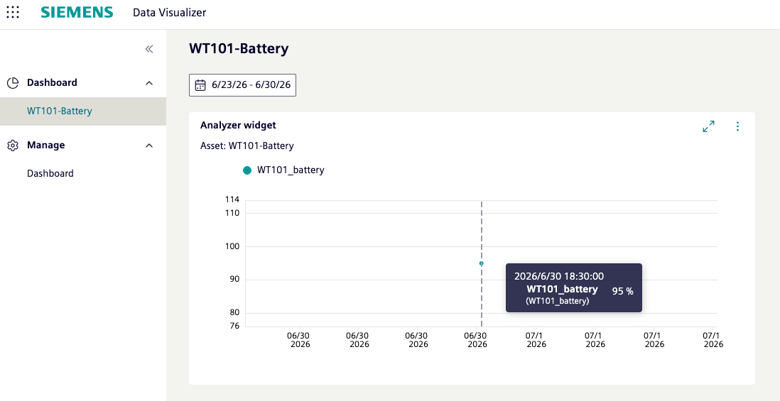
The dashboard now displays the Analyzer widget with the sensor data plotted as a time series. Hover over a data point to see the exact timestamp and value (e.g., 2026/6/30 18:30:00 — WT101_battery: 95%).
Note: You can add multiple widgets to the same dashboard, each visualizing different data points or using different widget types (e.g., Info card, Table, Heatmap). Use the Export button to download the dashboard as a PDF report.
Troubleshooting Tips
- BACnet devices not discovered: Ensure the Milesight Gateway and Desigo CC machine are on the same IP subnet, the UDP port 47808 is open, and the BACnet Driver is in “Normal” status.
- Agent Status not Connected: Verify the activation key was pasted correctly, the device distribution was assigned to Desigo CC/Cerberus DMS, and the application was synchronized.
- Wrong number of discovered points: Check the scope configuration (security groups). Only devices available to the IoT software user within the management and application views are discoverable.
- Upload button disabled: The upload button is grayed out when there are no differences between locally discovered points and points already uploaded. Make a configuration change and re-export to enable it.
- BACnet Device ID conflict: Each BACnet server on the network must have a unique Device ID. Change the Device ID on the Milesight Gateway if another BACnet device already uses the same ID.
Disclaimer
This document is designed to facilitate the seamless integration of Siemens and Milesight products. The product operation interfaces and screenshots referenced herein are provided for illustrative purposes; actual content may vary depending on the specific software or firmware versions in use. Please note that Siemens and Milesight each offer technical support exclusively for their respective products. The scope of integration support remains subject to the individual support policies of each vendor. We hope this guide helps streamline your integration process and enhances your experience with both Siemens and Milesight solutions. This document is provided for informational purposes only. Neither Siemens nor Milesight shall be held liable for any direct or indirect damages resulting from the use of this document or the integration process. All product names, logos, and brands are property of their respective owners. Unauthorized use or reproduction of any content in this document is prohibited.
Was this article helpful?
That’s Great!
Thank you for your feedback
Sorry! We couldn't be helpful
Thank you for your feedback
Feedback sent
We appreciate your effort and will try to fix the article